

Sep 11,2026
What Is Semiconductor Wafer Grinding?
Precision optical grinding requires close control over material removal, surface integrity, and dimensional accuracy. Even small defects can affect the quality of optical glass components, increase the workload of subsequent polishing, or make a finished part unsuitable for its intended application. Scratches, edge chipping, micro-cracks, and uneven surface roughness are among the problems manufacturers need to monitor during processing.
These defects rarely have a single cause. Abrasive condition, grinding tool selection, machining parameters, cooling, chip removal, and equipment stability can all influence the final surface. A grinding process that performs consistently on one type of glass may produce different results when the material, geometry, or processing requirements change.
For manufacturers, controlling surface defects means understanding how they develop and identifying which part of the process needs adjustment. This article examines common defects in precision optical grinding, explains their possible causes, and outlines practical methods for improving surface quality through appropriate tool selection and process control.
Surface quality is an important consideration when manufacturing optical glass components. The requirements vary according to the component's geometry, intended function, and subsequent processing stages. A part used in a precision optical assembly may require tighter control over surface condition than a component with less demanding optical or dimensional requirements.
Grinding directly influences the material's surface profile and can also affect the condition of the material beneath the visible surface. Scratches, pits, and other localized damage may remain after grinding if the process is not properly controlled. Some defects are visible during routine inspection, while others require more detailed examination.
Several aspects of surface quality deserve attention:
Surface roughness: The texture left by grinding influences the amount of material that may need to be removed during subsequent polishing.
Surface integrity: Cracks and subsurface damage can affect the condition of the processed glass beyond what is visible to the naked eye.
Edge quality: Chipping and irregular edges can compromise component geometry and create additional finishing requirements.
Dimensional accuracy: Uneven material removal can make it difficult to maintain the required dimensions and profiles.
Processing consistency: Variations between parts can increase inspection demands and complicate production planning.
A good grinding result is therefore not determined by material removal rate alone. Manufacturers need to consider the balance between processing efficiency, surface condition, and dimensional requirements. This balance becomes particularly important when producing components with small features, complex contours, or tight tolerances.
Different defects have different visual characteristics and may develop under different processing conditions. Identifying the defect correctly is the first step toward finding its cause. Treating every surface problem as a general grinding issue can lead to unnecessary adjustments without addressing the underlying source.
Scratches appear as visible lines or grooves on the processed surface. Their depth, length, and distribution can vary. Some are isolated marks, while others form repeated patterns across the grinding area.
One possible cause is the presence of loose abrasive particles or detached fragments within the contact area. Foreign particles and accumulated grinding debris may also become trapped between the tool and workpiece. When these materials move across the glass surface, they can leave unwanted marks.
The condition of the grinding tool is another factor worth checking. Abrasive distribution, local wear, and changes in the tool's working surface can affect how consistently material is removed. Scratches may also become more pronounced when chip evacuation is inadequate.
Manufacturers investigating this problem should examine the surface pattern rather than immediately changing all grinding parameters. Repeated directional marks, isolated scratches, and irregular grooves may point toward different sources. Checking the tool condition, cleaning the processing area, and reviewing cooling and debris removal can help narrow down the cause.
Pitting refers to small localized depressions or cavities on a glass surface. These defects may appear as scattered spots or concentrated areas of damage. Their size and distribution depend on the material and the conditions under which grinding takes place.
Localized material fracture is one possible explanation. Glass is a brittle material, and concentrated mechanical loading can cause small areas to break away rather than being removed through a controlled grinding action. Variations in abrasive contact or the presence of existing material imperfections may also contribute.
The first step in controlling pitting is to determine whether the damage is associated with the material itself, the grinding tool, or the processing conditions. Inspecting multiple areas of the workpiece can help establish whether the defects are isolated or follow a recurring pattern.
If pitting occurs repeatedly, manufacturers should review abrasive condition, grinding depth, and the stability of tool contact. Reducing excessive local loading and maintaining a consistent grinding process may help limit further surface damage.
Edge chipping occurs when small fragments break away from the edges of an optical glass component during machining. Unlike a surface scratch, a chip represents a localized loss of material and can affect the finished edge profile.
The problem is particularly relevant when processing thin glass, narrow features, or components with complex edge geometries. Excessive mechanical loading, unsuitable feed conditions, insufficient workpiece support, and unstable tool contact may all contribute to chipping.
The direction and location of the damage can provide useful clues. If chipping repeatedly occurs at the same processing stage or along a particular section of the edge, the manufacturer should review the corresponding tool path and contact conditions.
Control measures should focus on keeping grinding forces within an appropriate range. This involves matching the feed rate and grinding depth to the material and equipment, maintaining reliable workpiece support, and choosing a grinding tool suited to the required edge geometry.
Abrasive condition also deserves attention. A tool that no longer performs consistently may produce irregular contact and make edge quality more difficult to control.
Micro-cracks are small fractures that may develop on or beneath the visible glass surface. Subsurface damage can be especially difficult to identify because the affected area may not be apparent during a basic visual inspection.
These defects are associated with the mechanical stresses generated during grinding. When the local stress exceeds what the glass can withstand, brittle fracture may occur. Excessive grinding load, aggressive material removal, and unstable contact can increase the risk.
Thermal effects may also contribute. Local heat accumulation can create additional stress within the workpiece, particularly when cooling conditions and chip evacuation are inadequate.
Micro-cracks matter because their effects may extend beyond the immediate grinding operation. Depending on the component and its processing requirements, damaged material may need to be removed during subsequent finishing. If the damage is too extensive, additional finishing may not be sufficient to meet the required surface condition.
Controlling this problem requires attention to both mechanical and thermal conditions. Manufacturers should review the grinding depth, feed rate, tool condition, and cooling arrangement together rather than treating them as independent variables.
Where subsurface integrity is important, appropriate inspection methods should be included in the quality control process. Visual inspection alone may not reveal the full extent of the damage.
Uneven surface roughness occurs when different areas of a workpiece have noticeably different surface textures. Some sections may appear smoother, while others retain more pronounced grinding marks.
This variation can result from inconsistent abrasive contact, uneven tool wear, machine vibration, or changes in the relationship between the tool and workpiece. Inadequate control of grinding parameters may also cause different areas to experience different material removal conditions.
Tool wear is particularly important when the same grinding head is used over an extended production period. As the working surface changes, the contact condition may no longer remain consistent across the entire processing area.
Manufacturers should compare roughness measurements from different locations rather than relying on a single measurement point. If the variation follows a particular direction or processing path, the tool condition, machine stability, and workpiece positioning should be examined.
Consistent surface roughness depends on maintaining stable contact and using a grinding tool that matches the processing requirements. Regular inspection helps identify changes before they result in a larger number of nonconforming parts.
Thermal damage refers to surface or material changes associated with excessive heat during grinding. Depending on the material and the severity of the exposure, it may appear as discoloration, localized damage, or other changes in surface condition.
Friction between the grinding tool and workpiece generates heat. If cooling is insufficient or debris accumulates in the processing area, heat may not be removed effectively. High processing loads and unsuitable operating conditions can make the problem more pronounced.
Manufacturers should not assume that every surface mark is caused by heat. The material's condition, abrasive interaction, and other mechanical factors should also be considered during inspection.
A review of coolant delivery, chip evacuation, feed conditions, and grinding depth can help identify possible sources of thermal damage. The aim is to maintain suitable processing conditions and prevent excessive heat from building up at the grinding interface.
The defects described above may look different, but several underlying factors can influence more than one type of surface damage. Examining these factors together provides a more useful basis for process improvement.
Abrasive grit size influences the way a grinding tool interacts with the workpiece. Different processing stages require different material removal characteristics. A grit specification suitable for an initial grinding operation may not be appropriate for a finishing stage where a finer surface condition is required.
Tool condition is equally important. Changes in abrasive exposure, wear, or particle retention can affect grinding consistency. A worn or damaged working surface may produce irregular contact and uneven material removal.
Manufacturers should select diamond grinding tools for optical components according to the material, processing stage, required surface condition, and equipment configuration. Tool inspection should also form part of routine production checks, particularly when surface quality begins to vary.
Grinding speed, feed rate, and grinding depth determine how the tool interacts with the workpiece during material removal. These parameters influence the mechanical load, processing stability, and amount of material removed in each pass.
A feed rate that is too high for the existing tool and material combination may increase the grinding load. Excessive grinding depth can also concentrate stress in the contact area. On the other hand, changing parameters without considering production requirements may reduce efficiency without necessarily improving surface quality.
There is no single parameter combination that works for every optical glass component. Manufacturers need to consider material characteristics, workpiece geometry, tool specifications, and machine capability when establishing operating conditions.
Trial processing provides a practical way to evaluate changes. By adjusting one or a small number of variables at a time and inspecting the resulting surface, operators can better understand how each adjustment affects the grinding result.
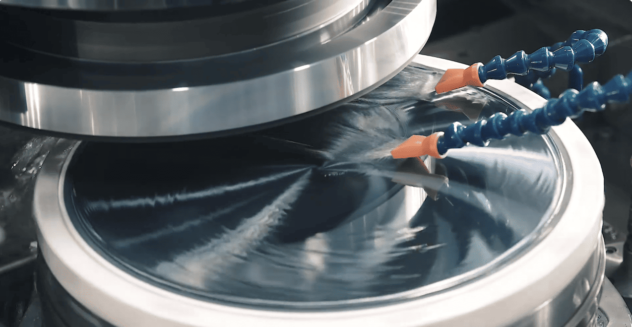
Cooling and chip removal are closely related to surface quality. Grinding generates heat and produces debris that must be managed during processing. If coolant does not reach the working area effectively, or if debris remains around the contact zone, the grinding process may become less stable.
Accumulated particles can interfere with the abrasive-workpiece interface and potentially cause secondary scratches. Inadequate cooling may also allow heat to build up, increasing the risk of thermal damage.
Manufacturers should check coolant delivery, the condition of the processing area, and the effectiveness of debris evacuation. These checks are particularly useful when scratches or thermal marks appear repeatedly despite otherwise stable machining parameters.
Even a suitable grinding tool may produce inconsistent results when the machine is not operating steadily. Spindle vibration, tool runout, incorrect installation, and unreliable workpiece support can all affect the contact between the tool and glass.
Tool runout may create variations in the effective contact condition during rotation. Vibration can also leave repeated marks or contribute to uneven material removal.
Regular inspection of the spindle, tool mounting, fixture condition, and workpiece positioning helps identify these problems. Manufacturers should verify that the grinding head is installed correctly and that the equipment is operating within its intended conditions.
Optical glass materials differ in their hardness, brittleness, and response to mechanical processing. Workpiece thickness and geometry also influence the way grinding forces are distributed.
Thin components and narrow edge features may require closer attention to workpiece support and tool contact. Complex profiles can introduce changes in the contact area as the tool follows the required geometry.
For this reason, a process developed for one type of optical glass should not automatically be transferred to another. Material properties, component shape, and the required finished condition should all be considered when selecting the tool and setting the grinding process.
Once the likely causes have been identified, manufacturers can develop a more targeted control approach. The objective is not simply to reduce grinding intensity, but to maintain a stable balance between material removal, surface condition, and production efficiency.
Grinding tool selection should begin with the workpiece material and the intended processing stage. Abrasive grit size, tool geometry, bond characteristics, and working condition all influence the grinding interaction.
Abrasive specifications should match the material removal requirements. Coarser grinding operations and finer finishing operations may require different tool characteristics. Using an unsuitable grit size can make it more difficult to achieve the required surface condition.
Tool condition should also be monitored throughout production. Manufacturers should inspect the working surface for abnormal wear, damage, or changes that may affect grinding consistency.
When evaluating precision diamond grinding tools, consider the following:
Whether the abrasive specification matches the material and processing stage.
Whether the tool geometry is suitable for the component's shape and machining area.
Whether the tool can be installed and operated under the equipment's specified conditions.
A suitable optical grinding tool selection process reduces the risk of using a tool that is poorly matched to the application.
Grinding parameters should be established according to the workpiece, tool, and equipment rather than selected from a general-purpose setting.
Feed rate and grinding depth are particularly important because they influence the mechanical load applied during material removal. Grinding speed also needs to be considered in relation to the tool specification and machine capability.
A practical optimization process involves:
Establishing a baseline using the current tool and operating conditions.
Recording surface defects and relevant inspection results.
Adjusting selected parameters in a controlled manner.
Comparing the resulting surface condition and processing efficiency.
Documenting the settings that produce consistent results.
This approach makes it easier to identify which changes improve the grinding result. It also reduces the risk of introducing new problems through multiple uncontrolled adjustments.
Cooling arrangements should provide adequate access to the grinding area and support the removal of heat and debris. The exact requirements depend on the machine, tool configuration, and workpiece.
Manufacturers should check whether coolant delivery is consistent throughout the operation. They should also examine whether debris is accumulating around the contact area or interfering with the grinding process.
Keeping the working area clean and maintaining effective chip evacuation can help reduce secondary scratches and improve processing stability. When thermal damage occurs, cooling conditions should be reviewed alongside grinding load and tool condition.
Stable tool installation and machine operation are essential for consistent grinding results.
Before production, operators should verify that the grinding head is securely mounted and correctly aligned. The spindle, fixture, and workpiece support should also be checked for conditions that could introduce vibration or uneven contact.
During production, unusual noise, visible vibration, or recurring surface patterns may indicate that the machine or tool condition needs attention.
Routine maintenance and timely tool inspection help prevent minor equipment problems from developing into repeated surface quality issues.
Surface inspection should be integrated into the production process rather than reserved for the final stage. Early detection makes it easier to identify when a defect first appears and which operation may have contributed to it.
Different inspection methods provide different information:
Microscopic inspection: Helps identify scratches, pits, edge chipping, and visible surface damage.
Surface roughness measurement: Provides quantitative information about surface texture.
Edge inspection: Helps identify chips, irregular profiles, and localized material loss.
Subsurface damage evaluation: Appropriate methods may be required when near-surface cracks or material damage are a concern.
Inspection results should be recorded together with the relevant tool and processing information. This allows manufacturers to compare different production runs and identify recurring patterns.
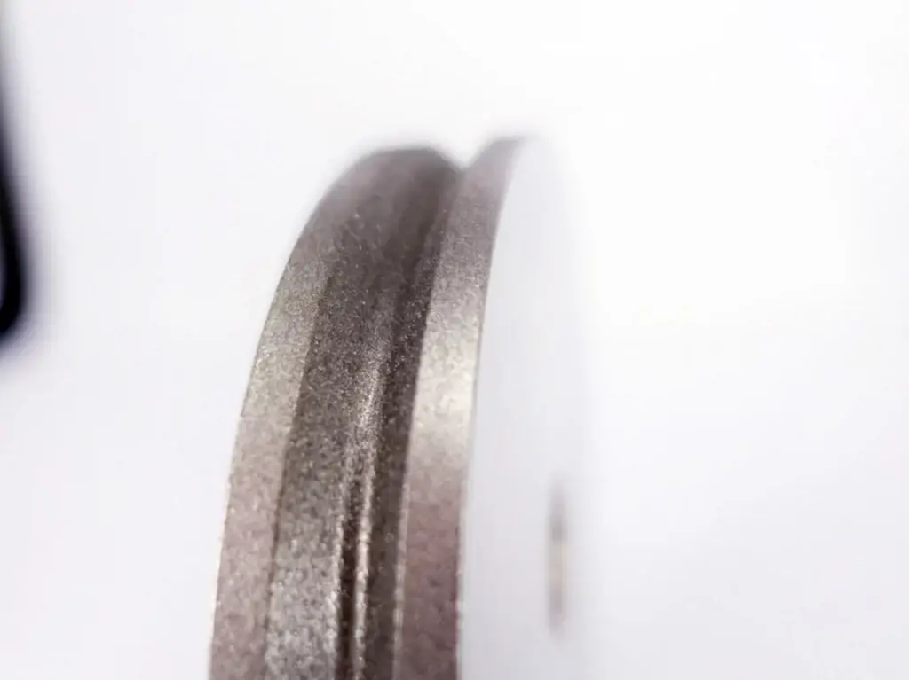
The grinding head is one of the factors that directly influences the interaction between the abrasive and the optical glass. Its abrasive characteristics, geometry, working condition, and compatibility with the equipment all need to match the intended application.
Abrasive sharpness influences how effectively a grinding tool removes material. A suitable abrasive condition helps maintain a more consistent grinding interaction, while changes in the working surface may affect material removal and processing stability.
For manufacturers evaluating a diamond grinding head for optical glass, tool selection should account for the material, required processing profile, and surface quality expectations. Sharpness should be considered together with grit size, bond characteristics, and the operating conditions of the machine.
Grit size is an important consideration when selecting a grinding tool. Different stages of optical glass processing may require different abrasive specifications because the material removal requirements and desired surface conditions are not the same.
Manufacturers should evaluate grit size in relation to the intended operation rather than assuming that a finer abrasive is always the best choice. The selected specification should support the required material removal while remaining compatible with the tool and equipment.
The geometry of a grinding head should match the component's shape and the area being processed. Small features, curved profiles, and narrow machining areas may require a tool with an appropriate size and configuration.
Equipment compatibility is also important. Mounting dimensions, tool structure, and operating requirements should be checked before the tool is introduced into production.
For applications involving precision optical glass, manufacturers can review Meijie's precision optics grinding head as a relevant product option. The selection should be evaluated against the actual workpiece geometry, processing requirements, and equipment configuration.
Controlling surface defects requires more than correcting individual problems as they appear. A consistent quality control process helps manufacturers identify recurring issues and understand how tool condition and operating conditions affect the final result.
A practical process should include regular inspection of grinding heads, recording of key machining parameters, and surface checks at appropriate production stages. When a defect appears, operators should document its location, appearance, and frequency rather than relying only on general descriptions.
Comparing inspection results with tool usage records and machining data can help identify patterns. For example, recurring scratches may justify checking abrasive condition and chip evacuation, while uneven roughness may require a closer examination of tool wear, spindle stability, and workpiece positioning.
The purpose of this process is to establish repeatable conditions for each application. Different optical materials and component geometries may require different control measures, so quality records should be specific enough to support meaningful adjustments.
Surface defects in precision optical grinding can result from several interacting factors, including abrasive condition, grinding parameters, cooling, chip removal, equipment stability, and material properties. Scratches, pitting, edge chipping, micro-cracks, uneven roughness, and thermal damage each require a different approach to diagnosis and control.
For optical glass manufacturers, consistent results depend on matching the grinding tool to the workpiece and maintaining stable processing conditions throughout production. Careful tool selection, controlled parameter adjustments, effective cooling, and appropriate inspection help reduce the risk of recurring defects.
Selecting a suitable precision optics grinding head is an important part of this process. Manufacturers evaluating grinding tools for optical components can refer to Meijie's precision optics grinding head product information and assess its suitability against their specific material, geometry, and equipment requirements.