
Oct 22,2026
How to Select a Diamond Grinding Head for Precision Optical Components
Dimensional accuracy is a critical requirement in precision optical grinding, particularly when components must meet tight tolerances or maintain complex contours. Even when a ground surface appears smooth, the finished part may still fall outside its specified dimensions because of positioning errors, tool wear, inconsistent material removal, or measurement differences. These problems can affect component fit, subsequent processing, and final inspection results.
Achieving consistent accuracy requires more than selecting a suitable grinding tool. Workpiece positioning, machine condition, tool installation, grinding parameters, and dimensional inspection must work together as a controlled process. When dimensional deviations occur, identifying their source is more effective than changing several machining conditions at once. A systematic approach helps manufacturers determine whether the problem originates in the setup, the grinding operation, or the measurement procedure.
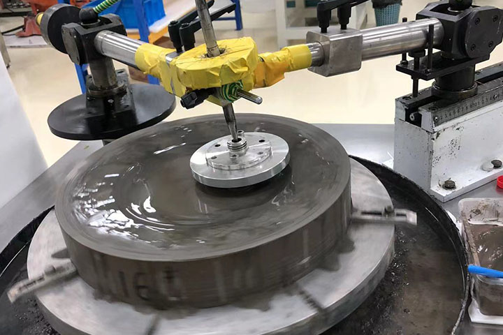
Dimensional accuracy in precision optical grinding describes how closely the finished component matches the dimensions specified in its engineering drawing. Depending on the component, these requirements may cover diameter, thickness, hole size, edge geometry, contour dimensions, or the position of specific features. The applicable tolerance defines the permitted deviation; the required accuracy should therefore be assessed against the drawing rather than a general assumption about what constitutes precision grinding.
Dimensional accuracy is also different from surface finish. Surface roughness describes small-scale variations in a surface, while dimensional tolerance concerns the permitted difference between a measured dimension and its specified value. Profile accuracy addresses whether the finished shape follows the required geometry. A component can have a relatively smooth surface yet still have an incorrect diameter or profile. Conversely, a dimension may fall within tolerance while the surface finish remains unsuitable for the intended application.
Several parts of the machining process influence the final result. Workpiece location determines how the component is referenced during grinding. Machine motion and spindle condition affect the relationship between the tool and the workpiece. Tool geometry, installation, and wear influence the material-removal process, while feed rate, grinding depth, and machining allowance affect how much material is removed. Measurement methods determine whether the finished dimensions are evaluated consistently.
These factors are interconnected. For example, adjusting the feed rate may not correct a dimensional error caused by an incorrectly established workpiece datum. Likewise, replacing a worn grinding head will not resolve a problem caused by inconsistent clamping. Effective precision grinding process control begins with understanding how the entire setup contributes to the measured result.
Dimensional errors do not always have a single cause. A part that repeatedly measures too large may indicate an incorrect setup offset, an unsuitable machining allowance, or an error in the measurement reference. Variation between nominally identical components may instead point toward inconsistent positioning, changing tool condition, or fluctuations in the machining process. The observed pattern provides a starting point for investigation, but measurements and equipment checks are needed to confirm the cause.
The workpiece must be located consistently relative to the machine and grinding head. If its reference surface is not seated correctly, or if the clamping arrangement allows movement during machining, the tool may remove material from an unintended position. This can produce dimensional deviations even when the programmed path and nominal machining parameters remain unchanged.
Clamping force also matters. Insufficient restraint can allow the component to shift, while inappropriate clamping may deform a delicate workpiece. The effect depends on the material, geometry, thickness, support arrangement, and machining forces. For optical components with curved surfaces or thin sections, the fixture should provide stable support without introducing avoidable distortion.
Machine motion, spindle condition, and tool installation influence the relationship between the grinding head and the workpiece. Abnormal spindle behavior, contamination at a mounting interface, incorrect seating, or excessive tool runout can affect the consistency of material removal. Wear in relevant machine components may also contribute to deviations that become more noticeable during repeated production.
Tool condition should be assessed alongside machine condition. A grinding head that has worn unevenly or no longer performs consistently may produce results different from those obtained when the tool was first installed. However, not every dimensional deviation is evidence of tool wear. Inspection should establish whether the tool, mounting arrangement, or machine is actually contributing to the problem.
Changes in feed rate, grinding depth, material allowance, or other operating conditions can alter the machining load and the amount of material removed. If these conditions vary between parts, dimensional consistency may suffer. Differences in how parts are measured can create another source of apparent variation, especially when operators use different reference points or apply different inspection procedures.
The following table connects common symptoms with practical checks. These are diagnostic starting points rather than definitive cause-and-effect rules.
| Observed problem | Possible factors to check | Recommended check |
|---|---|---|
| Dimensions consistently too large or too small | Datum selection, machine offsets, machining allowance, measurement reference | Verify the drawing datum, setup values, and actual material removal |
| Dimensions vary between workpieces | Clamping repeatability, tool condition, machine stability, parameter variation | Compare setup conditions, tool status, and recorded measurements |
| Profile deviations occur in different areas | Workpiece alignment, tool geometry, machine motion, machining path | Inspect alignment and tool condition, then compare the measured profile with the drawing |
A useful diagnosis should account for the component's geometry, the machine configuration, and the measurement method. Changing a tool or adjusting a parameter before checking these fundamentals can introduce additional variation and make the original cause harder to identify.
A stable machining setup provides the foundation for repeatable dimensional results. Before grinding begins, the workpiece datum, fixture location, and intended machining reference should be checked against the drawing and process requirements. The same reference should be maintained throughout the relevant operations. If the component is removed and repositioned between steps, the repeatability of that repositioning becomes important.
Machine readiness deserves equal attention. The spindle, relevant motion axes, tool mounting interface, and fixture should be inspected according to the machine manufacturer's procedures. Dirt or damage at a mounting surface can prevent a tool from seating correctly. Any suspected spindle or motion problem should be assessed using suitable inspection methods rather than corrected through arbitrary changes to the machining program.
The grinding head itself must be suitable for the machining operation. Its diameter, shank diameter, working length, profile, and abrasive grit size affect whether it can reach the required feature and operate appropriately within the available machining space. A tool that does not fit the equipment interface correctly, or whose geometry is unsuitable for the target feature, can make consistent material removal more difficult.
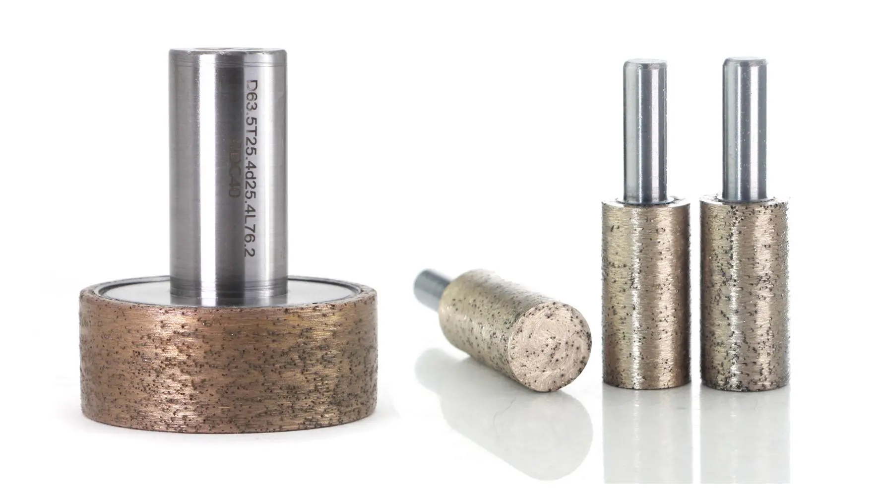
For applications involving precision optical components, a precision optics grinding head is one tool option to evaluate against the workpiece and equipment requirements. Meijie's product page lists grinding head diameters from Ø4 to Ø30 mm, shank diameters of Ø6 mm and Ø10 mm, and grit sizes from 100# to 3000#. These are the listed product ranges, not universal recommendations for every optical grinding operation. The appropriate configuration depends on the component, machining feature, machine interface, and required finish.
Tool installation and wear should also be monitored during production. A grinding head that was suitable at the beginning of a run may not maintain the same performance indefinitely. Inspection intervals should reflect the application, operating conditions, and observed tool behavior. If dimensional drift develops over time, comparing measurements with tool-use records can help establish whether tool condition is a contributing factor.
The key is to establish a repeatable baseline. When workpiece positioning, machine condition, and tool installation are stable, changes in the measured result become easier to associate with specific machining conditions. Without that baseline, it is difficult to tell whether a parameter adjustment has genuinely improved accuracy.
Grinding parameters influence both the rate of material removal and the conditions under which the tool contacts the workpiece. Spindle speed, feed rate, grinding depth, and machining allowance should therefore be considered together. A setting that works for one material or component geometry may not produce the same result on another, even when the same type of grinding head is used.
Spindle speed affects the operating conditions at the grinding interface. Its suitability depends on the tool specification, machine capability, workpiece material, and process requirements. Increasing speed does not automatically improve dimensional accuracy. The result must be evaluated alongside tool condition, machine behavior, and the quality of the finished component.
Feed rate influences how quickly the tool advances relative to the workpiece. A higher feed may increase material removal per unit of time, but it can also change machining load and the conditions under which the target surface is generated. A lower feed is not a universal solution to dimensional errors either. If the underlying problem is incorrect positioning or an unstable fixture, changing feed rate may have little effect on the actual source of the deviation.
Grinding depth and machining allowance determine how much material remains to be removed at each stage. An unsuitable allowance can complicate final dimension control, particularly when the process must accommodate variations in the incoming workpiece. Where the manufacturing process permits separate roughing and finishing operations, the allocation of material removal between stages should be established through process validation rather than assumed to follow a fixed ratio.
For reliable optical grinding dimensional accuracy, parameter optimization should begin only after the workpiece setup, tool installation, and measurement procedure have been checked. Establish a repeatable starting condition, then adjust a relevant variable while keeping other conditions as consistent as practical. Measure the resulting component and record the settings alongside the dimensional results. This makes it easier to identify whether the change improved accuracy, had no meaningful effect, or introduced another problem.
Trial results should be evaluated against the actual drawing requirements. A parameter combination that produces a good surface finish may still leave a critical dimension outside tolerance. Similarly, a dimension that passes inspection on one sample does not establish that the process will remain stable during a longer production run. Both dimensional results and other required quality characteristics should be considered before adopting a revised process.
Inspection is not simply the final step used to accept or reject a component. It provides the evidence needed to determine whether the grinding process is under control. Before measuring, the inspector should identify the critical dimensions, specified tolerances, datum references, and measurement locations defined by the engineering drawing. Without a consistent reference, two measurements may differ even when the physical component has not changed.
The measuring method must be appropriate for the feature being evaluated. A diameter, thickness, hole, and complex profile may require different inspection approaches. The measurement system should have suitable resolution and be maintained and calibrated according to the applicable procedures. Where the tolerance is tight, measurement uncertainty and repeatability become particularly important because they affect confidence in the reported result.
Measurement conditions also need to remain consistent. The component should be positioned correctly, and the inspection procedure should use the same relevant reference points. For delicate or irregularly shaped optical parts, the support arrangement and measurement contact can affect the result. Complex contours may require multiple measurement locations or a method capable of evaluating the relevant profile rather than relying on a single point.
A single conforming component does not demonstrate that the process will produce consistent results across a batch. Repeated measurements can reveal whether dimensions remain close to the target, gradually drift, or fluctuate from part to part. These patterns help determine whether further checks are needed on the fixture, grinding head, machine condition, or operating parameters.
When a component fails inspection, first verify that the drawing requirements and measurement procedure have been interpreted correctly. Repeat the measurement where appropriate and confirm that the datum and inspection method are consistent. If the deviation is confirmed, compare the result with setup information, tool condition, machining parameters, and previous inspection records. After a corrective action, measure the component again to verify the effect.
This approach helps distinguish an actual machining problem from a measurement inconsistency. It also creates a useful record of the relationship between process conditions and finished dimensions, making recurring problems easier to investigate.
When dimensional deviations occur, a consistent troubleshooting sequence reduces unnecessary tool changes and parameter adjustments. The objective is to confirm the measured problem, identify the most plausible contributing factor, and verify the result after corrective action.
Verify the measurement: Check the drawing tolerance, datum, inspection method, measuring equipment, and repeatability of the result. Confirm that the deviation is real before changing the process.
Inspect the setup and tool: Review workpiece positioning, clamping stability, tool installation, tool wear, and relevant machine conditions. Look for changes from the established machining baseline.
Review the process and confirm the result: Compare the actual machining parameters and material-removal records with the intended settings. Adjust a controlled variable where justified, then remeasure the workpiece and record the outcome.
The sequence should guide investigation rather than replace engineering judgment. Persistent or unexplained deviations may require a more detailed machine inspection, process review, or evaluation of the measurement system. Recording both the problem and the corrective action helps prevent repeated troubleshooting based on guesswork.
High dimensional accuracy in precision optical grinding depends on a repeatable process, not on a single tool specification or machining parameter. Stable workpiece positioning, suitable machine and grinding head conditions, controlled material removal, and consistent inspection all contribute to reliable results. When deviations occur, confirming the measurement and checking the setup before changing operating conditions makes the investigation more efficient.
For manufacturers processing precision optical components, the most useful improvement is a process that connects machining conditions with verified dimensional results. Suitable grinding tools remain an important part of that process, but their performance must be evaluated in the context of the actual workpiece and equipment. Meijie's precision optics grinding head provides product specifications for evaluating a potential tool configuration against those requirements.