
Aug 27,2026
What Is Wheel Bond and Why Does It Matter in Glass Grinding
Semiconductor ceramic components often require more than simple flat surfaces or drilled holes. Grooves, curved edges, recessed features, and other machined profiles may be needed to meet component drawings, assembly requirements, or equipment design specifications. Producing these features in hard, brittle ceramics requires careful control of the tool geometry, machining path, and material removal process.
Semiconductor ceramic groove machining and ceramic profile machining commonly involve diamond grinding tools because these tools are designed for processing hard materials. However, the appropriate method depends on the feature being produced, the ceramic material, the required dimensions, and the capabilities of the machine. A tool suitable for groove broaching may not be the best choice for every curved profile or narrow feature.
Understanding how machining methods, tool selection, and inspection work together helps manufacturers develop a process that meets the requirements of each component without relying on a single set of parameters for every application.
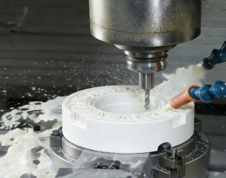
Grooves and profiles serve different geometric purposes, so their machining requirements are not identical. A groove is generally defined by its width, depth, cross-sectional shape, and position on the component. A machined profile, by comparison, may include curved edges, arcs, transitions, or a more complex external contour. Some components require both features, making tool access and dimensional control particularly important.
The difficulty increases when these features are produced in ceramic materials. Ceramics such as alumina, zirconia, silicon carbide, and silicon nitride are used in semiconductor equipment, but their machining behavior varies by material and grade. Their hardness can make material removal demanding, while their brittleness means that local stresses during machining may lead to edge chipping or surface damage.
Groove machining in ceramic components also presents practical limitations related to tool access. A narrow groove may require a tool with a small working diameter, while a deeper feature may require sufficient effective length to reach the target area. If the tool geometry does not match the feature, the process may produce an incorrect groove shape or make it difficult to maintain consistent dimensions along the full machining path.
Profile machining introduces additional considerations. The tool must follow the intended contour while maintaining the required geometry. Abrupt changes in direction, restricted access, or inconsistent material removal can affect the finished shape. The machine, workholding arrangement, tool configuration, and programmed path all influence the result.
These challenges should be assessed against the component drawing rather than treated as a single general problem. Groove width and depth, profile geometry, edge condition, and dimensional tolerances should be identified before selecting the machining method.
Diamond grinding for ceramic components is an important machining approach when hard ceramic materials need to be shaped or finished. Diamond abrasive is suitable for demanding material-removal applications, but the tool configuration and operating conditions must match the workpiece and the feature being machined.
The choice of machining operation depends on the required geometry. A groove may be produced through a suitable grinding or broaching operation, while a curved edge or external contour may require a different tool shape and controlled tool movement. Platform milling and other specified grinding operations may also be relevant to particular semiconductor ceramic components.
Computer numerical control (CNC) equipment can help guide a tool along a programmed path. For a profile, the path must correspond to the intended contour. For a groove, the process must control its position, width, depth, and cross-section. CNC control does not eliminate the need for appropriate tool selection or process verification; the final result still depends on machine capability, tool condition, workholding, and machining parameters.
The tool's physical dimensions are especially important. A tool that is too large may not reach a narrow feature or reproduce its intended geometry. A tool with insufficient effective length may not reach the required depth. Conversely, choosing a tool solely because it is small does not guarantee a suitable result, since rigidity, access, and the intended operation must also be considered.
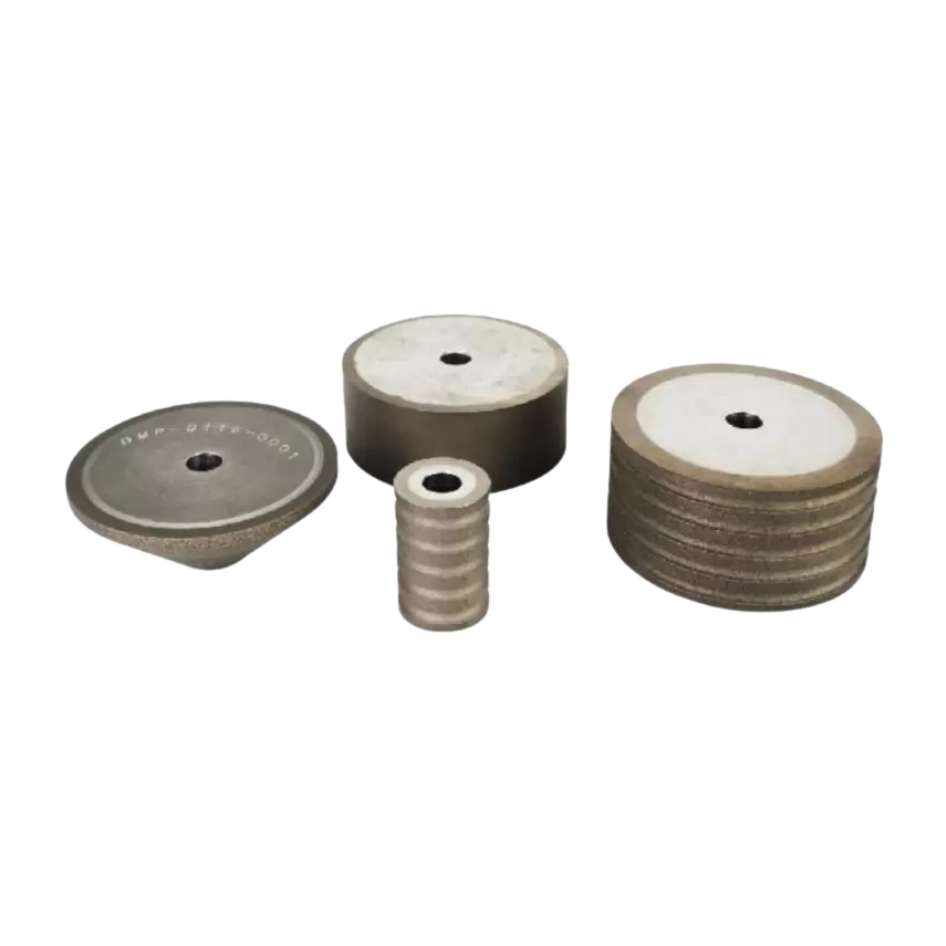
Meijie's semiconductor ceramic grinding head is listed for processing ceramic materials including alumina, zirconia, silicon carbide, and silicon nitride. Its specified applications include platform milling, arc edge grinding, thread grinding, inner hole grinding, and groove broaching. These applications make it a relevant option to evaluate when planning certain ceramic machining operations.
The product's listed parameters include a 10 mm shank diameter, an effective length of 25–60 mm, grit sizes from 60# to 400#, an equipment rotation speed of 9,000–28,000 r/min, a feed rate of 100–1,500 mm/min, and a grinding depth of 0.005–0.05 mm. These are product specifications, not a universal recipe for groove or profile machining. The suitable configuration and operating conditions must be confirmed for the intended feature, machine, and material.
When comparing methods, the main considerations are:
Feature geometry: The groove cross-section, depth, profile shape, and dimensional requirements.
Tool accessibility: Whether the tool can reach the target area with sufficient effective length and appropriate geometry.
Machine capability: The available motion control, workholding, spindle range, and process stability.
The selected method should be based on these factors together. A machining operation that works well for a shallow groove may not be appropriate for a deep slot or a profile with tight curvature.
Dimensional control begins with translating the component drawing into measurable machining requirements. For a groove, these may include width, depth, location, and cross-sectional geometry. For a profile, the relevant requirements may include contour dimensions, radii, transitions, and the relationship between the machined feature and adjacent surfaces.
Tool geometry is one of the first factors to check. The tool diameter and working shape affect the feature that can be produced, while the effective length determines how far the tool can reach into the workpiece. The shank and clamping arrangement must also be compatible with the equipment. These dimensions should be checked before machining rather than corrected through trial-and-error adjustments after an unsuitable tool has been installed.
The programmed toolpath is another key factor. A profile may require the tool to follow a continuous curve or a series of connected movements. Errors in the programmed path, coordinate setup, or workpiece positioning can create deviations from the intended contour. For grooves, the path must maintain the correct position and direction while controlling the material removed along the feature.
Machining parameters influence the removal process and the condition of the finished surface. Spindle speed, feed rate, and grinding depth should be considered together, with adjustments based on the ceramic material, tool specification, equipment, and feature geometry. Increasing feed rate or grinding depth without validating the resulting process may affect surface quality or dimensional consistency. Similarly, operating at a particular speed does not guarantee the same result across different tools and machines.
The following table summarizes the main controls and what should be verified.
| Control factor | Potential influence | Verification focus |
|---|---|---|
| Tool geometry | Groove shape, feature access, and achievable dimensions | Diameter, working shape, effective length |
| CNC toolpath | Contour accuracy and consistency | Path definition, positioning, local overcut |
| Grinding parameters | Material removal and surface condition | Speed, feed rate, grinding depth |
| Workholding and setup | Feature position and repeatability | Clamping, alignment, workpiece location |
| Inspection | Conformity to drawing requirements | Groove width, depth, profile dimensions |
Inspection should be based on the actual drawing and acceptance criteria. Depending on the feature, this may involve dimensional measurement, profile inspection, or examination of the machined edges and surfaces. A component can meet a nominal groove depth while still having unacceptable edge damage, so dimensional checks and surface-quality checks should not be treated as interchangeable.
Process consistency also depends on tool condition. Changes in tool wear can affect machining behavior and the dimensions produced over time. Establishing an appropriate inspection frequency and reviewing results across repeated parts can help identify changes before they lead to a larger batch of nonconforming components.
The objective is not to apply the most aggressive machining parameters, but to achieve the required geometry and surface condition within the capabilities of the equipment and tool.
Edge chipping is one of the concerns in ceramic groove machining. Because ceramic materials are brittle, local stresses during material removal can damage the edge of a groove or the boundary of a machined profile. The extent of damage depends on the material, feature geometry, tool condition, and machining process. A chipped edge should therefore be investigated in context rather than attributed automatically to one operating parameter.
Dimensional deviation is another possible issue. A groove may be too wide, too deep, or incorrectly positioned, while a profile may not follow the intended contour. Potential contributing factors include tool geometry, workpiece alignment, machine condition, tool wear, and programming errors. Repeatedly changing the feed rate without checking these other factors may fail to address the actual cause.
Surface damage can also occur during grinding. The appearance and severity of the damage depend on the material and the machining conditions. Inspection should establish whether the issue is limited to the visible edge or also affects the machined surface. Where the component has defined surface or dimensional requirements, the evaluation should use those criteria rather than a general visual judgment alone.
A structured troubleshooting process helps separate possible causes:
Inspect the tool: Check for wear, damage, and a mismatch between the tool geometry and the required feature.
Review the setup and process: Confirm workpiece positioning, toolpath, and the selected machining parameters.
Verify the result: Measure critical dimensions and examine edge and surface condition against the component requirements.
Changes should be evaluated systematically. If several variables are altered at once, it becomes difficult to determine which change improved or worsened the result. Where necessary, a controlled trial using a representative workpiece can help establish whether the tool configuration and machining conditions are suitable before full production.
Tool selection and process control are related, but they are not substitutes for each other. A suitable tool cannot compensate for incorrect positioning or an unsuitable toolpath. Likewise, a well-programmed path cannot overcome a fundamental mismatch between the tool geometry and the feature being produced.
Tool selection should start with the geometry of the feature rather than the product name alone. For a groove, the required width, depth, cross-section, and location help determine the tool dimensions and working shape. For a profile, the contour, corner geometry, and accessibility of the target surface must be considered. The same tool should not be assumed suitable for every feature on a component.
The ceramic material and the required finished condition are also important. Alumina, zirconia, silicon carbide, and silicon nitride should not automatically be treated as interchangeable machining materials. The material grade, component geometry, and specified quality requirements can affect the choice of tool and operating conditions. The appropriate grit size and grinding parameters should therefore be confirmed against the actual application.
Tool dimensions need to match the machine and the machining task. Relevant checks include the tool diameter, shank diameter, effective length, clamping arrangement, and permitted operating range. For deep or narrow features, reach and access may be critical. For more complex profiles, the tool must be able to follow the required contour without interfering with adjacent surfaces.
The machining operation itself must also be considered. Drilling, hole grinding, reaming, groove broaching, and profile grinding are different operations, even when they involve similar tools or workpiece materials. Selecting a product because it is described as a ceramic grinding head is not sufficient; its documented applications and dimensions should be reviewed.
For example, Meijie's grinding head for semiconductor ceramic hole machining is specified for peck drilling, hole grinding, hole reaming, and groove broaching. Its listed head diameter is 0.5–5 mm, shank diameter is 6 mm, effective length is 2–20 mm, grit size is 100#–600#, and grinding depth is 0.005–0.02 mm. The product page does not specify its rotation speed or feed rate, so these values should not be inferred.
This product may be worth evaluating for suitable small-feature or hole-related operations, but its specifications do not establish that it is suitable for every groove or complex profile. The intended operation, required dimensions, and machine setup still need to be checked.
A practical tool-selection review should cover the following:
| Selection factor | Questions to confirm |
|---|---|
| Feature geometry | What are the required groove dimensions or profile shape? |
| Tool dimensions | Are the diameter, shank, and effective length suitable? |
| Material and quality | What ceramic is being machined, and what quality criteria apply? |
| Machine compatibility | Are the clamping method and operating conditions compatible with the equipment? |
| Process validation | Can the proposed configuration meet the drawing requirements in a representative trial? |
A trial and subsequent inspection provide evidence that the proposed tool and process are suitable. Where a component has several different features, each operation should be evaluated on its own requirements instead of assuming that one tool configuration will provide the best result for all of them.
Semiconductor ceramic groove machining and ceramic profile machining require a coordinated approach to tool geometry, machining paths, operating parameters, and inspection. The right process depends on the dimensions and shape of the feature, the ceramic material, and the machine's capabilities. Diamond grinding heads can support several types of ceramic machining, but their documented applications and specifications should guide selection.
For manufacturers, the practical priority is to match the tool to the required feature, validate the machining conditions, and inspect both dimensions and surface condition. This approach provides a more reliable basis for producing grooves and profiles that meet component drawing requirements.